
Substation Design & Physical Layout
Interconnection queues aren't held up by a shortage of megawatts. They're held up by a shortage of engineers who can produce a substation package. We produce the layout, the grounding design, the protection and control drawings, and the documentation that gets a substation reviewed and built.
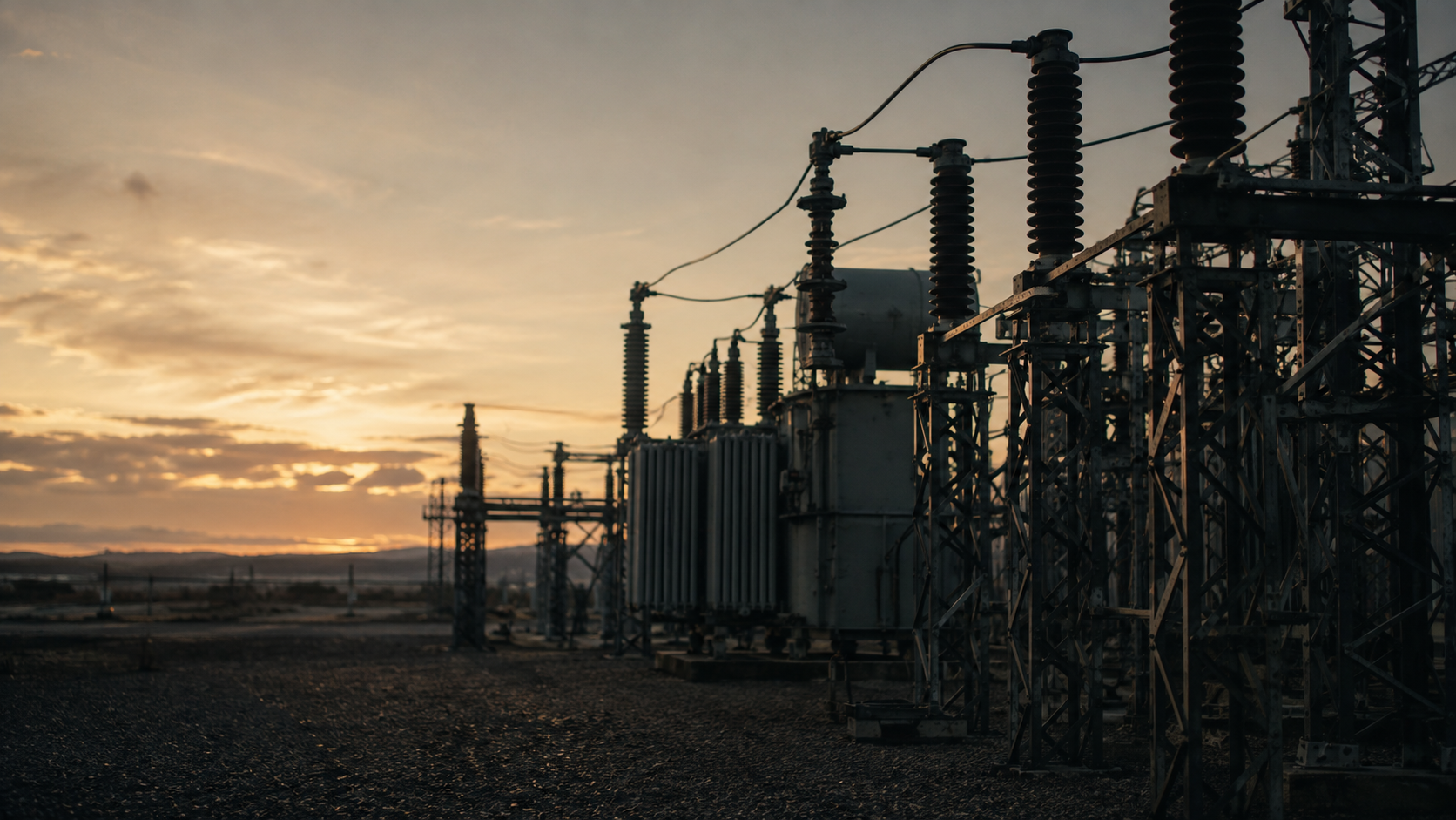

Concrete deliverables, not vague promises.
Physical layout
- General arrangement drawings: plan, section and elevation
- Equipment layout with phase spacing and working clearances
- Bus arrangement design: single bus, main and transfer, ring, breaker-and-a-half
- Electrical clearance verification for the applicable BIL and voltage class
- Structural steel layout for bus supports, dead-end structures and equipment stands
- Equipment foundation plans and anchor bolt layouts
- Control building layout and cable trench routing
- Site plan integration with access, security fencing and drainage
Grounding and lightning protection
- Ground grid design with conductor sizing and spacing
- Step and touch potential analysis to IEEE 80
- Soil resistivity interpretation and two-layer soil modeling
- Ground grid drawings with connection details and test well locations
- Direct stroke shielding design: masts, shield wires, rolling sphere analysis
- Surge arrester application and placement
Protection and control
- AC and DC schematic diagrams
- Protection and metering single-line and three-line diagrams
- Relay panel layouts and wiring diagrams
- Control building panel arrangement and elevations
- Cable and conduit schedules with routing
- Terminal block and interconnection wiring lists
- Protective relay setting calculations and coordination
- SCADA and RTU point lists
Studies and calculations
- Short circuit and fault duty calculation
- Equipment rating and duty verification
- Bus and conductor ampacity and thermal sizing
- Bus mechanical short-circuit force and support spacing
- Auxiliary AC and DC load calculation and battery sizing
- Voltage drop and station service design
- Insulation coordination and BIL verification
Documentation and submission
- Equipment specifications and datasheets for procurement
- Bill of materials and bill of quantities
- Construction drawing packages issued for construction
- Utility interconnection submission packages
- As-built drawing conversion after commissioning
A one-line diagram and a site boundary is enough to start. In practice we work from whatever stage the project has reached: a utility interconnection requirement letter, a preliminary equipment list, a geotechnical and soil resistivity report, an existing substation's record drawings for an expansion, or a marked-up satellite image showing where the station is going. Where the design intent isn't fixed, we can work from the load and voltage requirements and propose a bus configuration rather than executing a prescribed one. Where you already have a utility standard drawing set, we work to it.
Codes & standards
IEEE 80 (grounding), IEEE 998 (direct stroke shielding), IEEE 605 (bus design), IEEE 1127 (physical design), IEEE C37 series (switchgear and protection), IEEE 485 (battery sizing), NESC (ANSI C2) clearances, NERC reliability standards where the facility is bulk electric system, IEC 61936 and IEC 60071 for IEC-governed markets, and the interconnecting utility's own design standard where one is published. Where a utility publishes a standard drawing set and construction specification, that document governs: we build the package to their format rather than ours, and maintain a format record per utility we've submitted to, so a second project with the same utility moves faster than the first.
Full service engineering design. Delivered remotely.
- 01
Start with a bounded request
Send what you have — sketches, GIS/CAD files, pole data, spreadsheets. A named engineer reviews it and confirms a scoping timetable.
- 02
Agree scope, standards & criteria
Work begins once a written SOW sets deliverables, assumptions, standards and who owns each engineering decision.
- 03
Produce with visible controls
Assumptions, RFIs and progress are logged as they happen, not buried inside the drawing set.
- 04
Independent QA & handoff
A second reviewer checks the package against the SOW before a revision-tracked transmittal ships.
EPC contractors delivering substation scopes on a design-build basis
Renewable developers needing collector substations and points of interconnection designed for grid connection
Utilities and cooperatives with more capital projects than in-house engineering capacity
Independent power producers and data center developers requiring dedicated substations
Engineering consultancies absorbing substation workload without adding headcount for a project cycle
Does a substation package need a PE seal?
For utility submission and for construction, almost always, and utilities scrutinize the engineer of record more closely on substations than on nearly anything else. We produce the design, calculations, drawings and full package; sealing is by your engineer of record. Where you don't have one, tell us at scoping and we'll structure the deliverable and the engagement so your reviewing engineer has everything needed to take responsibility for it. We would rather resolve this before the work starts than at submission.
What voltage classes do you work at?
Distribution and collector substations through transmission class. Tell us the voltage and the interconnecting utility at scoping: the utility's design standard has more effect on the shape of the package than the voltage class does.
Can you work from an existing substation's record drawings for an expansion?
Yes, and brownfield expansion is common work. Where record drawings are incomplete or predate later modifications, we identify the gaps and tell you what field verification is needed rather than designing against a record we can't trust. Where you have point cloud data of the existing yard, we can work directly from it.
Do you do the grounding study, or just the drawings?
Both. Ground grid design with step and touch potential analysis to IEEE 80 is part of the service, not a separate specialist referral. Soil resistivity testing itself is a field activity carried out by your survey partner; we work from the resistivity data.
How long does a substation package take?
A distribution substation general arrangement and grounding design is typically three to five weeks. A full collector substation package with protection and control is usually eight to twelve weeks. Every project is quoted with a fixed date and a defined deliverable list before work starts.
Have a substation design & physical layout project to scope?
A sketch, a photo, a spreadsheet: send what you have and we’ll take it from there.