
Renewable-energy grid interconnection and power-system studies
A renewable developer and owner's engineer taking a 120 MWac solar plus storage project through a Southwestern U.S. ISO/RTO interconnection queue.
- Input received
- The validated interconnection request and POI/capacity data, utility-supplied network cases and contingency lists, and solar/BESS/inverter/plant-controller/transformer model data in the required PSS/E, PSLF or equivalent format.
- Delivered
- Interconnection application exhibits and a model register, a load-flow/thermal/voltage/contingency study report, a short-circuit duty table and protection-coordination inputs, a reactive-capability and STATCOM assessment, and a utility comment-response matrix.
- Timeline
- Ten Pathworks production weeks after validated network cases, queue data, equipment models and utility criteria. Excludes utility and ISO/RTO review time between cycles.
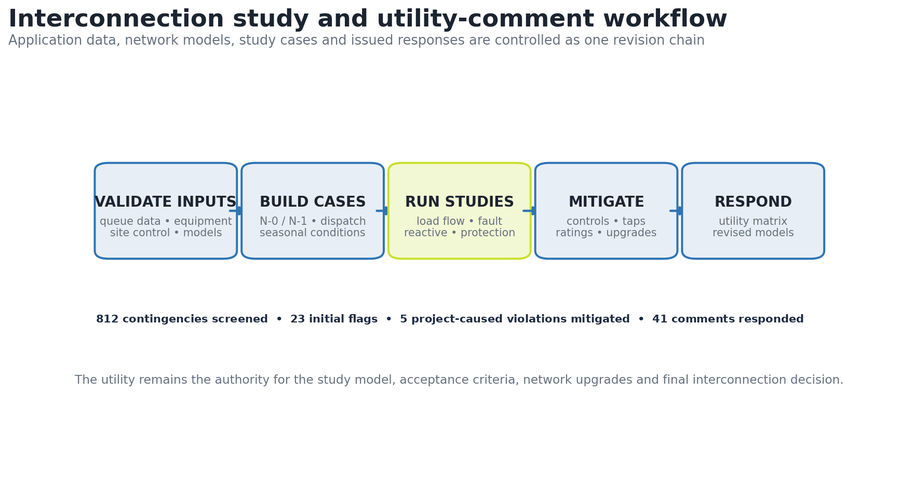
An interconnection evidence chain runs from application data through equipment models, study cases, contingencies, violations, mitigation, revised models and utility response, with a model register recording source, version, checksum and owner for every submitted file. The representative package supports a controlled 120 MW export basis, mitigates five project-caused violations, and logs 41 utility comments responded through three controlled cycles.
- Secured export
- 120 MW
- Contingencies
- 812
- Comments responded
- 41
- Study support
- 10 weeks
The engineering problem
The application data identifies project capacity but does not prove acceptable system performance. Solar and storage must be represented correctly in seasonal network cases, charging and export dispatches, fault studies, reactive-power tests and protection coordination. The challenge is not simply running software: the model, assumptions, contingencies, monitored elements, acceptance criteria, mitigation and utility comments must be reproducible, because a result that cannot be traced to a case and input revision cannot support an interconnection decision.
Design parameters and calculation basis
| Maximum export | 120 MW at 230 kV POI |
|---|---|
| Storage | 60 MW / 240 MWh; charging and discharging cases represented |
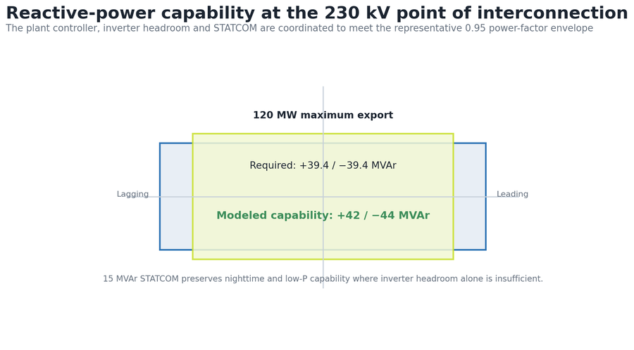
| Power factor target | 0.95 leading / lagging at maximum export |
| Reactive requirement | 120 × tan(cos⁻¹ 0.95) = 39.4 MVAr |
| Modeled capability | +42 / −44 MVAr at POI after plant losses |
| POI fault duty | 19.20 kA existing + 0.56 kA project = 19.76 kA |
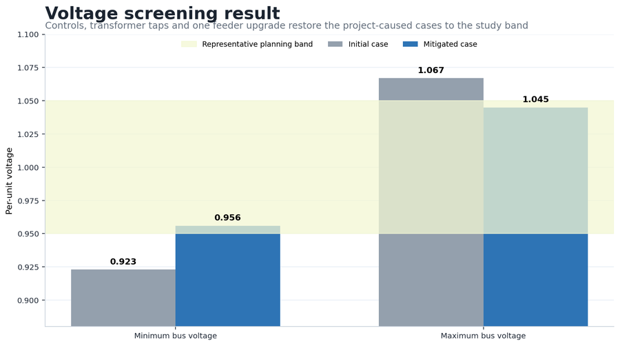
| Voltage result | 0.923–1.067 pu initial → 0.956–1.045 pu mitigated |
| Contingencies | 812 screened; 23 flags; 18 pre-existing; five project-caused |
Key design decisions
BESS charging, idle and discharging cases are all modeled, since a single maximum-export case cannot establish network impact. Pre-existing violations are separated from incremental project impacts before proposing upgrades. Transformer taps, plant-controller setpoints and inverter headroom are used first; the 15 MVAr STATCOM is added only where low-power and nighttime reactive capability remains insufficient. Breaker and transformer ratings are verified against the corrected fault and thermal cases before issue, and every utility comment is linked to model, report section, drawing and response rather than treated as an email-only change.
Design and quantity control
| Study gate | Initial finding | Controlled action | Final evidence |
|---|---|---|---|
| Steady state | 23 flags | Separate 18 pre-existing; mitigate five project-caused | No remaining project-caused violation |
| Voltage | 0.923–1.067 pu | Tap, controls and one feeder upgrade | 0.956–1.045 pu |
| Reactive | ±39.4 MVAr required | Coordinate inverter headroom + STATCOM | +42 / −44 MVAr |
| Short circuit | 19.20 kA existing | Add 0.56 kA project contribution | 19.76 kA < 40 kA rating |
| Utility comments | 41 comments | Three model / report cycles | 41 responded |
QA steps and evidence
| QA gate | Acceptance test | Evidence / result |
|---|---|---|
| Model integrity | Source case, revision and checksum recorded | Complete model register |
| Case coverage | Dispatch and contingency matrix complete | 812 screened events |
| Violation control | Each flag classified and mitigated | Five project-caused issues closed |
| Equipment duty | Fault and thermal duty below ratings | 19.76 kA vs 40 kA POI breaker |
| Comment closure | Response linked to evidence | 41 comments responded / three cycles |
Revision record
| Release | Trigger | Change made | Controlled outcome |
|---|---|---|---|
| Cycle 1 | Utility model validation | Corrected dispatch, transformer and monitor data | Study case accepted |
| Cycle 2 | Steady-state / reactive comments | Added feeder mitigation and STATCOM basis | Voltage and PF criteria satisfied |
| Cycle 3 | Protection / model comments | Updated fault data, one-lines and response package | 41 comments responded |
Result and calculation trail
The representative interconnection package supports a controlled 120 MW export basis for a 120 MWac solar plus 60 MW / 240 MWh storage project. Five project-caused steady-state violations are mitigated, voltage cases improve from 0.923–1.067 pu to 0.956–1.045 pu, ±0.95 power-factor support is demonstrated, and 41 utility comments are logged and responded through three controlled cycles. Acceptance of the study and the interconnection decision remain with the transmission provider.
Reactive requirement: Q = 120 MW × tan(cos⁻¹ 0.95) = 39.4 MVAr. Reactive margin: +42 − 39.4 = +2.6 MVAr lagging; 44 − 39.4 = 4.6 MVAr leading. POI fault duty: 19.20 + 0.56 = 19.76 kA, or 49.4% of a 40 kA rating. Project-caused finding rate: 5 ÷ 812 = 0.62% of screened contingencies.
Pathworks prepared a representative 230 kV interconnection support package for a 120 MW solar plus storage project, controlling network cases, load flow, short circuit, reactive capability, protection inputs and utility comments through one auditable model and response register.
More case studies
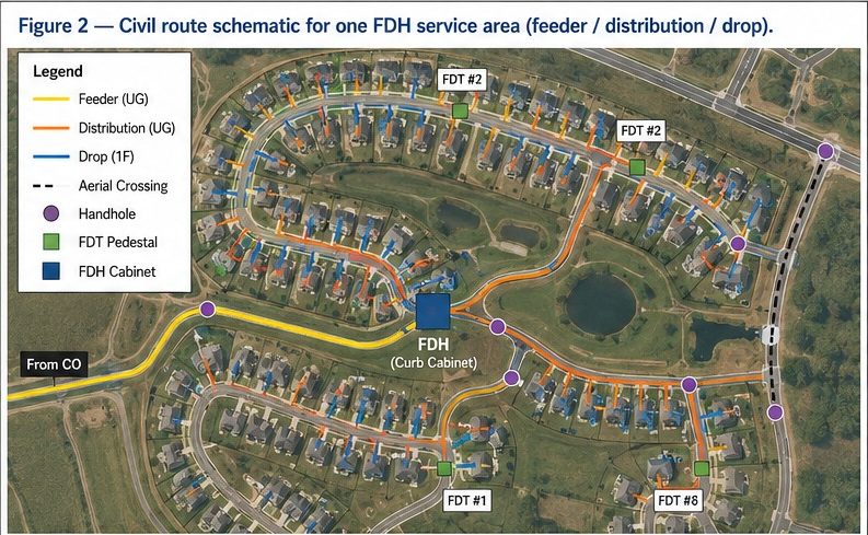

Greenfield FTTH design for 500 homes, full OSP package from plat to BOM
Built to standard US ILEC/CLEC practice: a two-stage 1:4/1:8 split localizes fault response to a single FDT instead of the whole feeder, construction runs underground-first to meet HOA aesthetic requirements, and 20–30% spare fiber is held at every tier so the network can absorb infill lots without a re-trench. The design closes with 7.4 dB of optical margin against the 28 dB GPON Class B+ budget, enough headroom for a future 1:64 upgrade at a subset of FDTs.
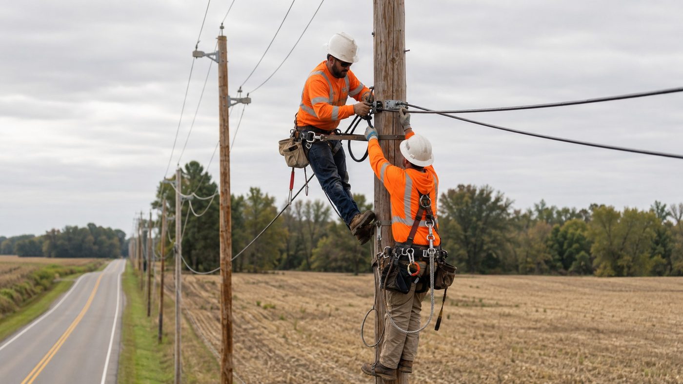
Rural greenfield FTTH design for a 500-location BEAD service area
A two-stage 1:32 split architecture assigns all 500 approved locations to complete XGS-PON paths across 512 terminal ports. Route optimization reduces the seed alignment from 35.7 to 33.0 miles, a 7.6% reduction, while the modeled planning cost falls from $9,460 to $8,940 per passing and the worst modeled path retains 4.74 dB of N2 optical margin.
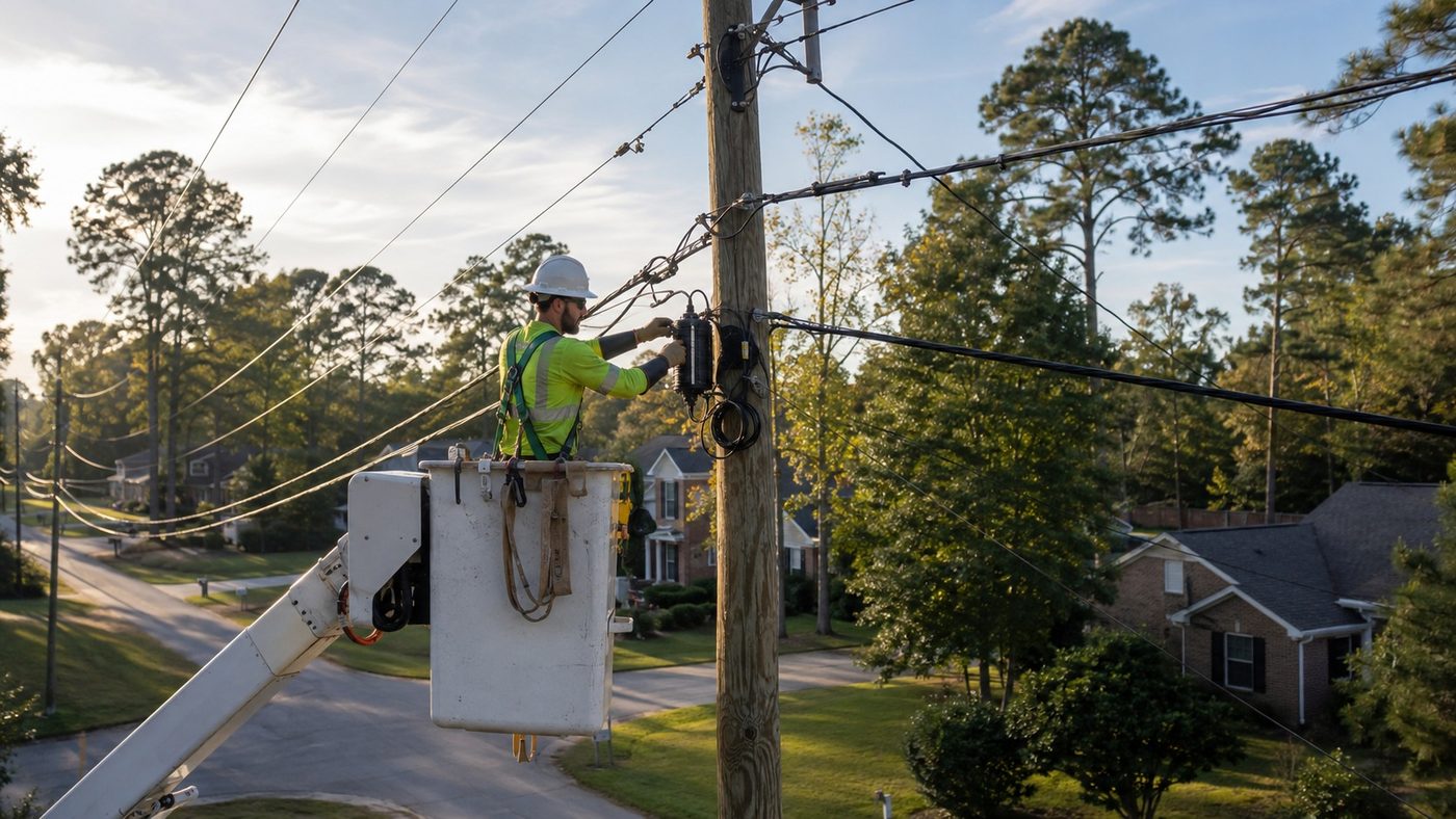
Aerial FTTH design and pole make-ready analysis
A pole-by-pole evidence record separates clean attachment candidates from conditions that require transfer, rearrangement, guying review or replacement. The modeled review identifies 226 make-ready or data conflicts across 1,946 poles; design adjustments resolve 141 before application packaging, including 15 avoided pole-replacement candidates, reaching 92% first-submission readiness.