
Utility Conflict Analysis: Reading a Composite Utility Drawing Before a Grading Plan Locks In
A composite utility drawing looks complete right up until a grading plan collides with something nobody flagged. Here's how to read one properly before that happens.
Pathworks Engineering Team
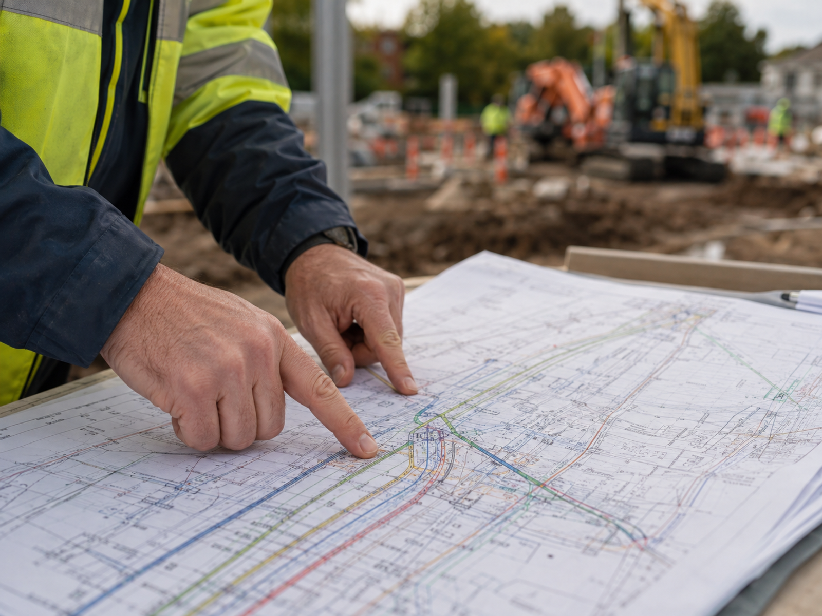
A grading plan that looks entirely clean when reviewed in isolation can still turn out to be unbuildable the moment it is properly overlaid against everything already installed in the ground on that site. Utility conflicts discovered during active construction (an unmarked gas line intersecting a proposed storm drain alignment, a water main sitting six inches above the elevation where a new sanitary sewer lateral needs to cross beneath it) are consistently among the most expensive and schedule-damaging discoveries a civil construction project can experience, and the great majority of them were genuinely discoverable at the design stage, had a properly constructed composite utility drawing been in place before the grading plan was finalized.
This article works through what a composite utility drawing actually requires to function as a real conflict-detection tool rather than a superficial reference exhibit, and why the sequencing of this analysis relative to grading plan development matters as much as the analysis itself.
What a Composite Drawing Actually Requires
A composite utility drawing is not simply multiple utility record drawings stacked together into the same CAD file at the same scale: that overlay is a reasonable and necessary starting point, but it is not, by itself, a finished conflict analysis, and treating it as one is where a great deal of false confidence enters the design process. A composite drawing that genuinely functions as a conflict-detection tool requires several additional layers of rigor.
A common horizontal and vertical datum confirmed across every source drawing. Utility record drawings originating from different utility owners (the local water district, the gas utility, various telecom and cable providers, the electric utility) are frequently referenced to different horizontal datums, or, more commonly and more dangerously, carry no reliable vertical elevation data at all, having been drawn purely as a plan-view record without any depth information ever having been field-verified. Overlaying these record drawings without first confirming they share a common datum, or without explicitly acknowledging where vertical data is simply absent, produces a drawing that visually looks coordinated and professional but is not actually telling a reviewer anything reliable about the vertical conflicts that matter most.
Confirmed versus assumed depth explicitly distinguished, and carried visually through the drawing. Utility record drawings routinely either omit installed depth entirely or provide only the depth that was originally specified in the design documents rather than the depth at which the utility was actually installed in the field (and the two are not reliably the same, particularly for older installations. A composite drawing that draws every utility line with identical line weight and visual confidence, regardless of whether that specific segment's depth was field-verified through potholing or is merely assumed from incomplete record data, actively hides exactly the risk information the drawing exists to surface in the first place. Depth confidence) verified, assumed from design record, or entirely unknown: should be a distinct, visible attribute on the drawing itself, not a footnote buried in a separate report that a reviewer working quickly from the drawing alone will never see.
Explicit crossing analysis performed at every point of intersection, not merely visual plan-view overlap. Two utility lines crossing in plan view are not automatically in genuine conflict: the actual question that matters is vertical clearance at that specific crossing station, and answering that question requires real elevation data at the crossing point itself, not an inferred "typical" depth extrapolated from elsewhere along the utility's run. Every plan-view crossing between a newly proposed utility and an existing one should be explicitly resolved to a stated vertical clearance figure, with a documented confidence level for that figure, before the grading plan built around it is considered genuinely final.
Field locate data from the 811 One-Call process reconciled against record drawings, not treated as a substitute for them. Field-painted utility locate marks reliably confirm horizontal position at the time of marking but rarely provide any reliable depth information, and the marks themselves fade or get physically disturbed by ongoing grading and construction activity well before construction actually reaches that specific station on a multi-phase project. Locate data is a valuable supplement to a design-phase composite drawing that was already built with care; it is not a substitute for having built that composite drawing properly well before mobilization, and relying on locates alone as the primary conflict-detection method effectively defers all conflict discovery to the moment excavation actually begins: precisely the point at which discovering a conflict is most expensive.
Why Sequencing the Analysis Correctly Matters as Much as the Analysis Itself
Utility conflict analysis delivers its greatest value when it is performed *before* the grading plan is finalized, rather than being run as a final verification check against an already-completed design. This sequencing distinction matters enormously in practice: a conflict discovered while the grading plan is still in an active, editable design state can typically be resolved through a routing adjustment, a minor grade change, or a revised crossing detail: all changes that are relatively inexpensive to make on paper. The identical conflict, discovered only once construction is already underway, usually means a field change order, a construction delay while the design team develops a resolution under schedule pressure, and in the worst realistic case, an actual utility strike with its associated safety risk, repair cost, and potential regulatory reporting obligation.
This is not merely a matter of catching the same problem slightly earlier: early discovery and late discovery of the identical utility conflict represent fundamentally different cost and risk categories, not points on the same continuum. A conflict caught in design review costs a redline. The same conflict caught by an excavator bucket costs a repair, a delay claim, and potentially a safety incident report.
Common Conflict Patterns Worth Specifically Watching For
Certain conflict patterns recur often enough across projects to be worth flagging explicitly during composite drawing review, rather than only discovering them through generic crossing-by-crossing analysis. Gravity-flow utilities (storm drainage and sanitary sewer) are particularly prone to conflicts because their elevation is dictated by hydraulic grade requirements rather than by convenient clearance from other utilities, meaning a storm line's required invert elevation frequently cannot simply be adjusted to avoid a conflict without cascading grade changes through the entire downstream system. Utility corridors that have been used repeatedly over decades for successive utility installations (a common pattern along many older public rights-of-way) tend to be more congested than record drawings suggest, because informal or undocumented installations sometimes occurred outside the formal permitting process that would have generated a reliable record drawing. And any utility crossing near a structure's foundation or a retaining wall footing deserves particular scrutiny, because the geotechnical and structural design of that footing may have made assumptions about surrounding soil conditions that a utility trench crossing nearby could invalidate if not properly coordinated.
Have a project like this to scope?
A sketch, a photo, or a rough spreadsheet is enough to start.
Start a ProjectWhere This Sits Relative to Our Grading and Earthwork Work
Utility conflict analysis sits directly upstream of the cut-and-fill and grading work discussed in From Topo Survey to Grading Plan: a grading plan that is internally consistent on its own terms, with clean drainage patterns and reasonable earthwork balance, is still only half-validated if it has not also been checked carefully against a properly constructed composite utility drawing, regardless of how carefully the earthwork itself was calculated using the methods discussed in our companion post on earthwork volume takeoffs.
We build composite utility drawings as a distinct, explicit deliverable ahead of grading plan finalization specifically so that conflicts are surfaced while they remain cheap and straightforward to resolve on paper, rather than being discovered by a construction crew mid-excavation. See our Civil & Structural Engineering Services page for how we scope this work as part of a broader civil design engagement.
Conclusion
A composite utility drawing that merely overlays record drawings from multiple utility owners onto a single sheet provides the visual appearance of coordination without necessarily providing the substance of genuine conflict detection. Real conflict analysis requires a confirmed common datum, an explicit and visible distinction between verified and assumed depth data, station-specific crossing resolution rather than plan-view overlap alone, and field locate data used to supplement (not substitute for) a properly built design-phase drawing. Performed early, before the grading plan is finalized, this analysis turns an expensive field discovery into an inexpensive paper redline.
References
- Common Ground Alliance: Best Practices for Damage Prevention
- ASCE 38: Standard Guideline for Investigating and Documenting Existing Utilities (Subsurface Utility Engineering Quality Levels)
- Related reading: From Topo Survey to Grading Plan: What Happens Between Field Data and Drawings
- Related reading: Earthwork Volume Takeoffs: Why the Grid, Cross-Section, and TIN Methods Don't Agree
- Pathworks services: Civil & Structural Engineering Services
Related articles
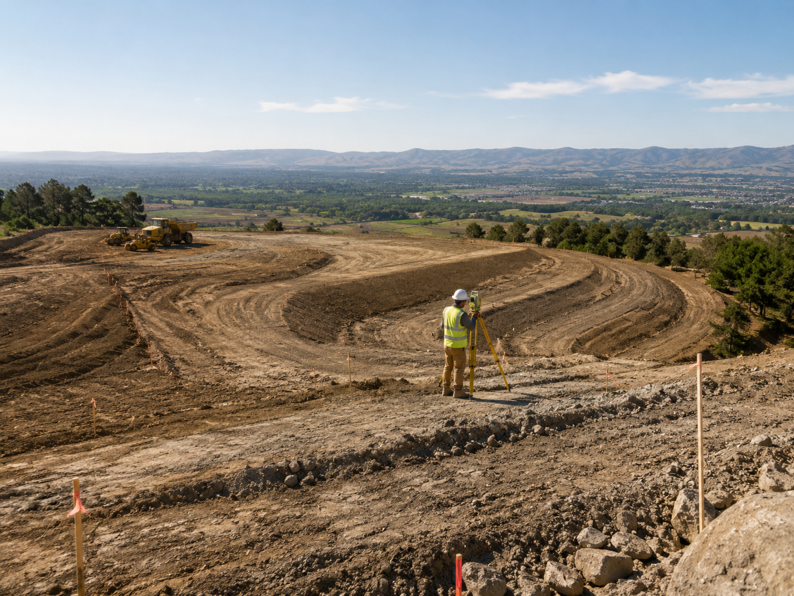
Earthwork Volume Takeoffs: Why the Grid, Cross-Section, and TIN Methods Don't Agree, and Which One to Trust
The grid method, the cross-section method, and the TIN method rarely agree on the same site. Here's which one to trust and why.
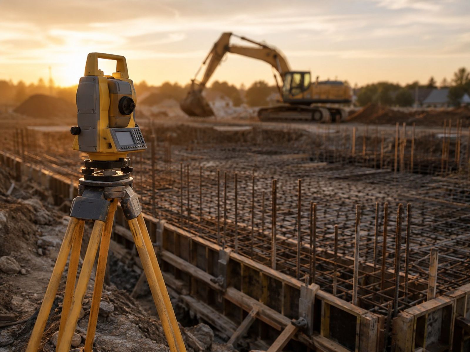
Cut and Fill Calculations, Demystified
Cut and fill numbers drive real budget and logistics decisions, but the calculation itself is often treated as a black box. Here's what's actually happening inside it.

From Topo Survey to Grading Plan: What Happens Between Field Data and Drawings
Survey points don't turn into a grading plan by themselves. Here's the actual sequence of decisions between a field dataset and a permit-ready drawing.