
FTTx Network Design: From HLD to Construction-Ready OSP Engineering
A practical guide to FTTx network design, covering HLD, LLD, splitter planning, fiber topology, BOQ development, QA/QC and construction-ready OSP documentation.
Pathworks Engineering Team
A successful FTTx network is more than a collection of lines on a map. It is the result of deliberate architecture, accurate geospatial design, sound fiber-capacity planning and construction-ready documentation that allows field teams to build the network efficiently and operators to maintain it over the long term.
For FTTH and broader FTTx deployments, the design process typically progresses from High-Level Design (HLD) through detailed Low-Level Design (LLD), fiber topology and splice planning, Bill of Quantities development, QA/QC and final construction documentation.
This article explains how those stages fit together and what makes an OSP fiber design practical, scalable and buildable.
1. Start with the Right FTTx Architecture
The High-Level Design establishes the overall network strategy before detailed engineering begins.
At this stage, the objective is to define how the service area will be covered, how feeder and distribution capacity will be allocated, where major passive elements will sit and how the network can grow without unnecessary redesign.
Typical HLD considerations include:
- OLT, POP or headend location
- Service-area and cluster boundaries
- Feeder and distribution architecture
- Proposed fiber routes
- Splitter strategy and split ratios
- Preliminary fiber counts
- Major splice and distribution points
- Estimated homes passed or premises served
- Spare capacity for growth and restoration
The shortest route is not automatically the best route. A strong HLD balances capital cost, optical performance, constructability, available infrastructure, maintainability and future expansion.
2. Translate the HLD into a Detailed OSP Low-Level Design
The LLD turns the network concept into the engineering detail required for implementation.
This is where the design becomes street-level and structure-specific. The engineer must account for the actual route, available poles or ducts, civil infrastructure, road crossings, parcels, buildings and practical locations for network equipment.
Depending on the project, an FTTx LLD may include:
- GIS or CAD route design
- Pole, duct and trench routing
- Manholes and handholes
- Cable lengths and fiber counts
- Splice closures
- FAT, FDT or terminal locations
- Splitter locations
- Building and parcel information
- Drop routes
- Road crossings
- Slack requirements
- Structure IDs and construction notes
A useful benchmark is simple: can a construction crew take the issued design to site and build from it without repeatedly returning to engineering for missing information?
If the answer is no, the design is not yet construction-ready.
3. Engineer the Fiber Topology, Not Just the Route
A geographic route shows where the cable travels. The logical fiber topology explains how the network connects.
A clear single-line diagram or fiber schematic helps engineers, splicers and field teams understand how the network progresses from the headend through feeder cables, closures, splitters, distribution cables, terminals and subscriber drops.
A strong fiber topology should make it easy to verify:
- Cable continuity
- Fiber counts
- Branching points
- Closure relationships
- Splitter relationships
- Downstream distribution
- Network hierarchy
- Spare capacity
The geographic LLD and logical fiber topology should always agree. A mismatch between the two can create confusion during construction, splicing and as-built reconciliation.
4. Treat Splitter Placement as an Engineering Decision
Splitter placement has a direct impact on fiber utilization, drop lengths, enclosure capacity, splice quantities, optical loss and long-term maintenance.
Depending on the operator's architecture, a 1:32 service split may be implemented as a centralized splitter arrangement or through staged splitting such as 1:4 followed by 1:8.
The correct choice depends on the network and should consider:
- Subscriber density
- Feeder-fiber utilization
- Distribution-cable requirements
- Drop distances
- Splice quantities
- Enclosure capacity
- Optical budget
- Fault isolation
- Maintenance access
- Future growth
The best design is not necessarily the one with the fewest cable meters. It is the one that achieves the required service capacity while balancing CAPEX, field simplicity, optical performance and scalability.
5. Plan Fiber Counts for Current Demand and Future Growth
Designing only for today's take rate can create expensive problems later.
The required fiber count should consider more than the immediate subscriber demand. Engineers should also evaluate spare capacity, restoration requirements, future infill, additional splitters and the possibility of later network expansion.
A practical planning approach considers:
Required fibers + network architecture + spare capacity + restoration strategy + forecast growth.
The correct spare-fiber policy varies by operator and network type, but it should always be deliberate rather than inherited from a drawing template.
6. Design for Constructability
A route can look perfect in CAD and still be difficult or impossible to build.
Constructability review should therefore be part of the engineering process, not an activity left entirely to the construction team.
Typical considerations include:
- Road and railway crossings
- Existing utilities
- Duct availability and occupancy
- Pole suitability and make-ready requirements
- Chamber and handhole capacity
- Private-property access
- Safe work areas
- Cable bend radius
- Practical splice locations
- Permit and right-of-way constraints
Have a project like this to scope?
A sketch, a photo, or a rough spreadsheet is enough to start.
Start a ProjectField verification, survey data, aerial imagery and reliable GIS information can all help identify these constraints before construction begins.
A minor routing adjustment during design is usually inexpensive. The same change after permitting, procurement or mobilization can cause schedule delays, redesign and additional cost.
7. Build the BOQ from the Engineering
The Bill of Quantities should be derived from the actual design rather than prepared as a disconnected estimate.
Depending on the project, the BOQ or BOM may include:
- Feeder fiber cable
- Distribution fiber cable
- Drop cable
- Ducts and microducts
- Poles and associated hardware
- Manholes and handholes
- Splice closures
- Splitter assemblies
- FAT or FDT equipment
- Connectors and adapters
- Slack storage
- Route markers and labels
- Civil-work quantities
When the route design, fiber topology and BOQ are aligned, procurement and construction teams have a much clearer picture of the actual project requirements.
This reduces one of the most common causes of implementation delay: discovering during construction that issued material quantities do not match the network being built.
8. Apply QA/QC Before Issue for Construction
Design QA/QC should evaluate engineering logic, not only drafting quality.
Before an FTTx design is issued, the review should check:
- Fiber continuity
- Cable capacity
- Splitter utilization
- Splice logic
- Route completeness
- Naming conventions
- Constructability
- BOQ consistency
- Optical-budget assumptions
- Compliance with client standards
Even small inconsistencies can propagate downstream. A cable ID mismatch between the LLD, fiber SLD and splice schedule may create field confusion and later make as-built documentation harder to reconcile.
Independent design review helps identify those issues before they reach construction.
9. Deliver a Complete Construction-Ready Package
The strongest FTTx workflows connect every engineering stage:
HLD → LLD → Fiber Topology → Splice Plan → BOQ → QA/QC → Construction → As-Builts
The final package should give implementation teams the information they need to execute the project efficiently and provide network operators with documentation that can be maintained after handover.
Typical final deliverables may include:
- HLD and LLD drawings
- GIS and CAD files
- Fiber single-line diagrams
- Splice schedules and fiber assignments
- BOQ or BOM
- Construction notes
- Redlines
- As-built documentation
- QA/QC records
FTTx and OSP Design Support from Pathworks Engineering
Pathworks Engineering supports network operators, EPC contractors and engineering firms with remote FTTx and OSP engineering services, including HLD and LLD development, GIS/CAD production, fiber route design, fiber topology and splice documentation, BOQ/BOM preparation, QA/QC, redlines and as-built documentation.
Our focus is straightforward: produce engineering deliverables that are technically sound, clearly documented and practical for the teams that must permit, price, construct, splice and maintain the network.
If your organization has an upcoming FTTH or FTTx deployment, a design backlog or a need for additional OSP engineering capacity, Pathworks Engineering can support a defined pilot scope and scale with your delivery requirements.
Related articles
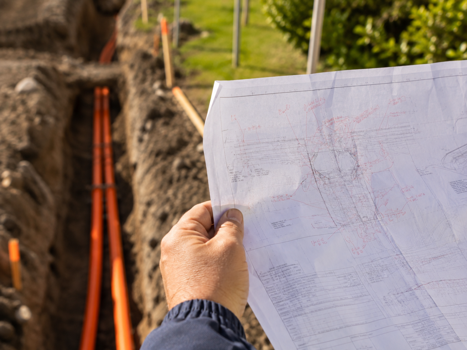

As-Built Redlining: Why the Built Network Stops Matching the Design, and How to Control the Drift
The network in the field and the network on the drawing start drifting apart the moment construction begins. Here's how to control that drift instead of discovering it years later.
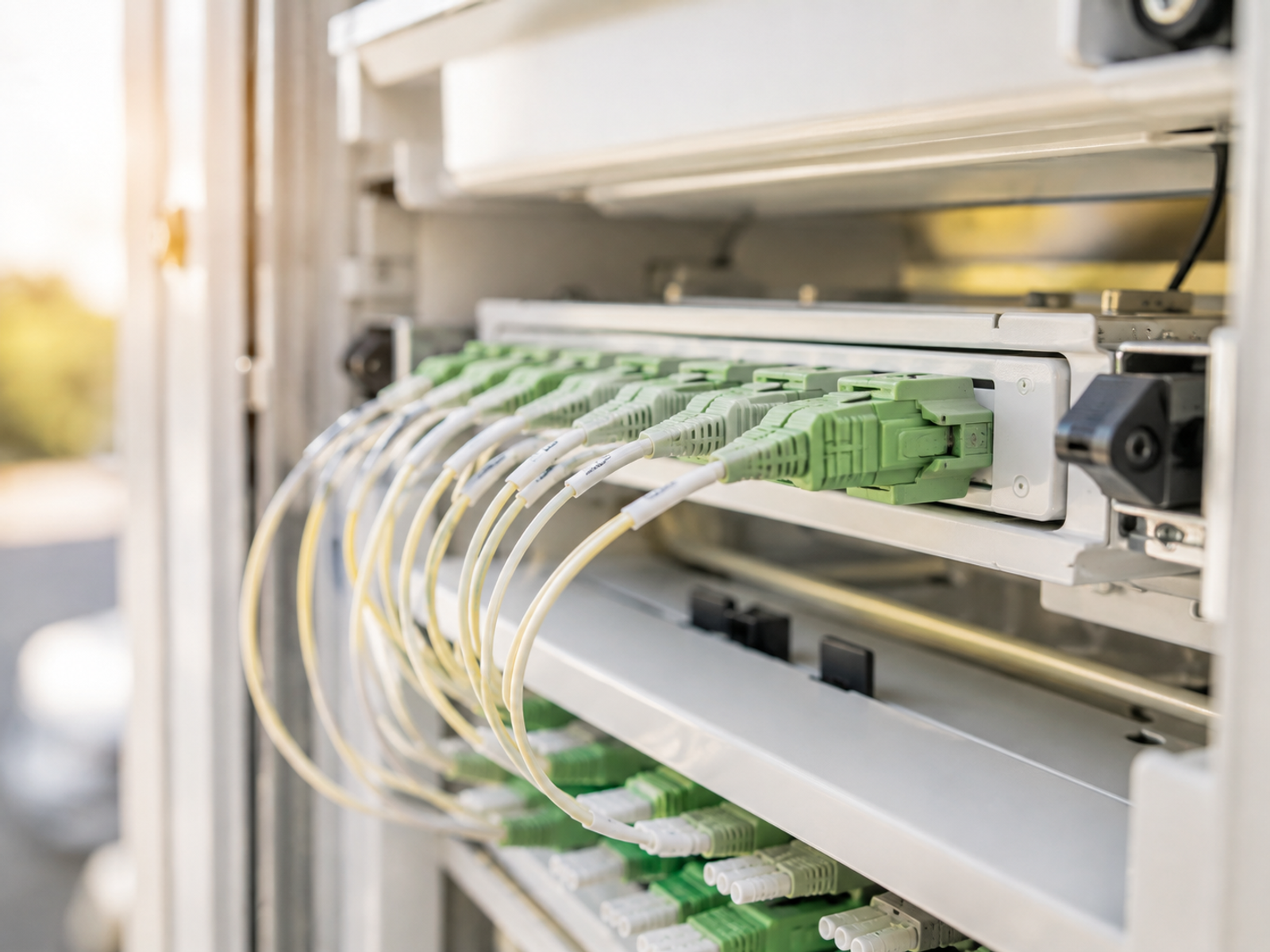
GPON Power Budgets: Sizing Split Ratios Against Real Receiver Sensitivity, Not the Datasheet Ceiling
Sizing a split ratio off the datasheet ceiling looks fine on paper and fails in the field. Here's how to budget against real receiver sensitivity instead.
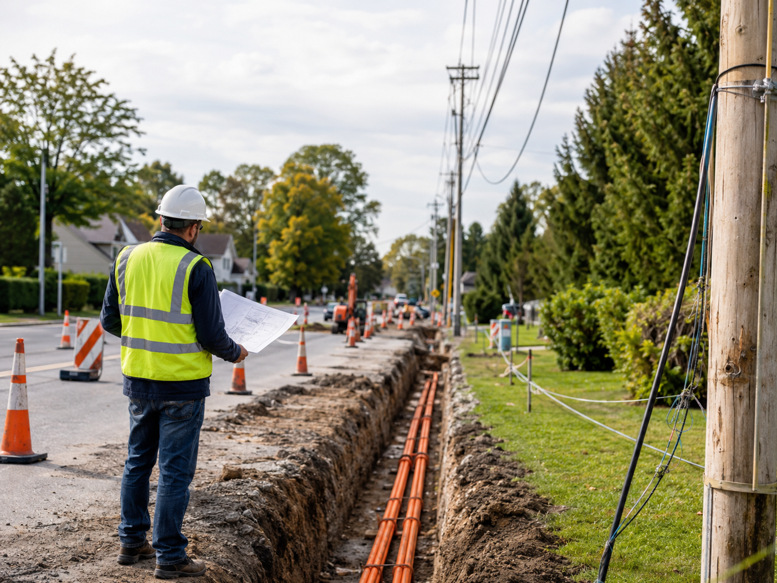
OSP Route Selection: The Real Cost Model Behind Underground vs. Aerial
A per-foot cost comparison hides most of what actually determines whether an aerial or underground route finishes on schedule and on budget. Here's the data that belongs in the decision instead.