
Designing a Passive Meet Me Room for 666 Homes: What It Actually Takes
We recently completed the passive optical design for a Meet Me Room serving a 666 unit residential development across 18 floors. Here's what went into it, and why some of the choices might not be what you'd expect.
Pathworks Engineering Team
Most FTTH conversations start and end with "we're running fiber to every unit." That part is easy to say. The part nobody talks about is the room where all those fibers actually meet, and whether the design in that room still makes sense five internet service providers and ten years from now.
We recently completed the passive optical design for a Meet Me Room (MMR) serving a 666 unit residential development across 18 floors. Here is what went into it, and why some of the choices might not be what you'd expect.
Start with what the building owner should NOT own
The first decision on a project like this is not technical, it is philosophical: should the building own active networking equipment, or should it stay purely passive?
We went fully passive. No OLTs, no switches, no UPS, no precision cooling, nothing that needs a maintenance contract or a technician on call. The building owner installs and owns the fiber infrastructure. Every ISP that wants to serve the building brings its own active electronics and connects at a clearly defined demarcation point.
This single decision shapes almost everything else in the design. It removes ongoing operational cost from the building. It keeps the MMR technology neutral, so the building isn't locked into one ISP's hardware roadmap. And it means the room itself needs almost nothing beyond structure, lighting, and two maintenance power outlets. No UPS, no HVAC, no standby generator load.
Two risers, eight cables, 768 cores
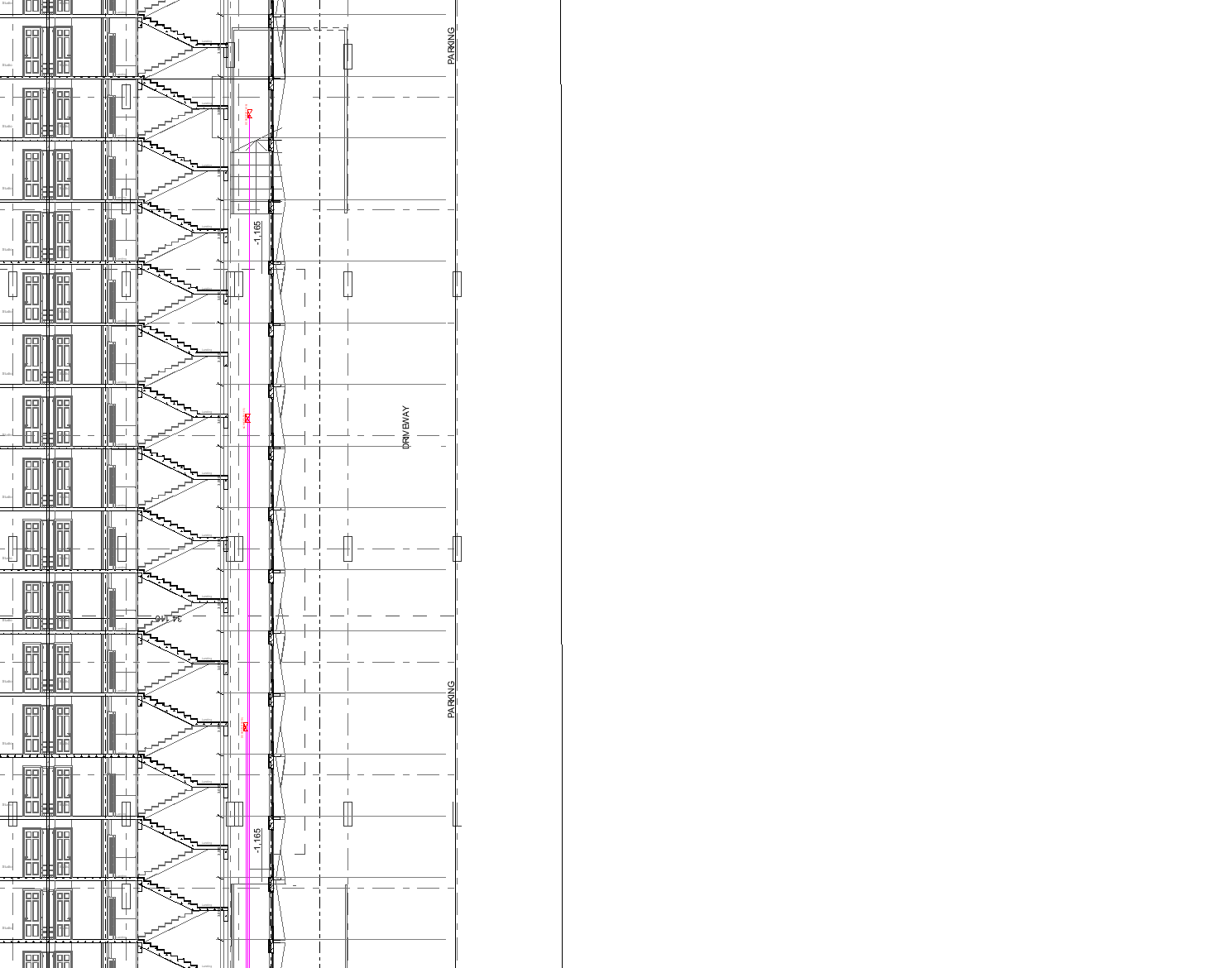
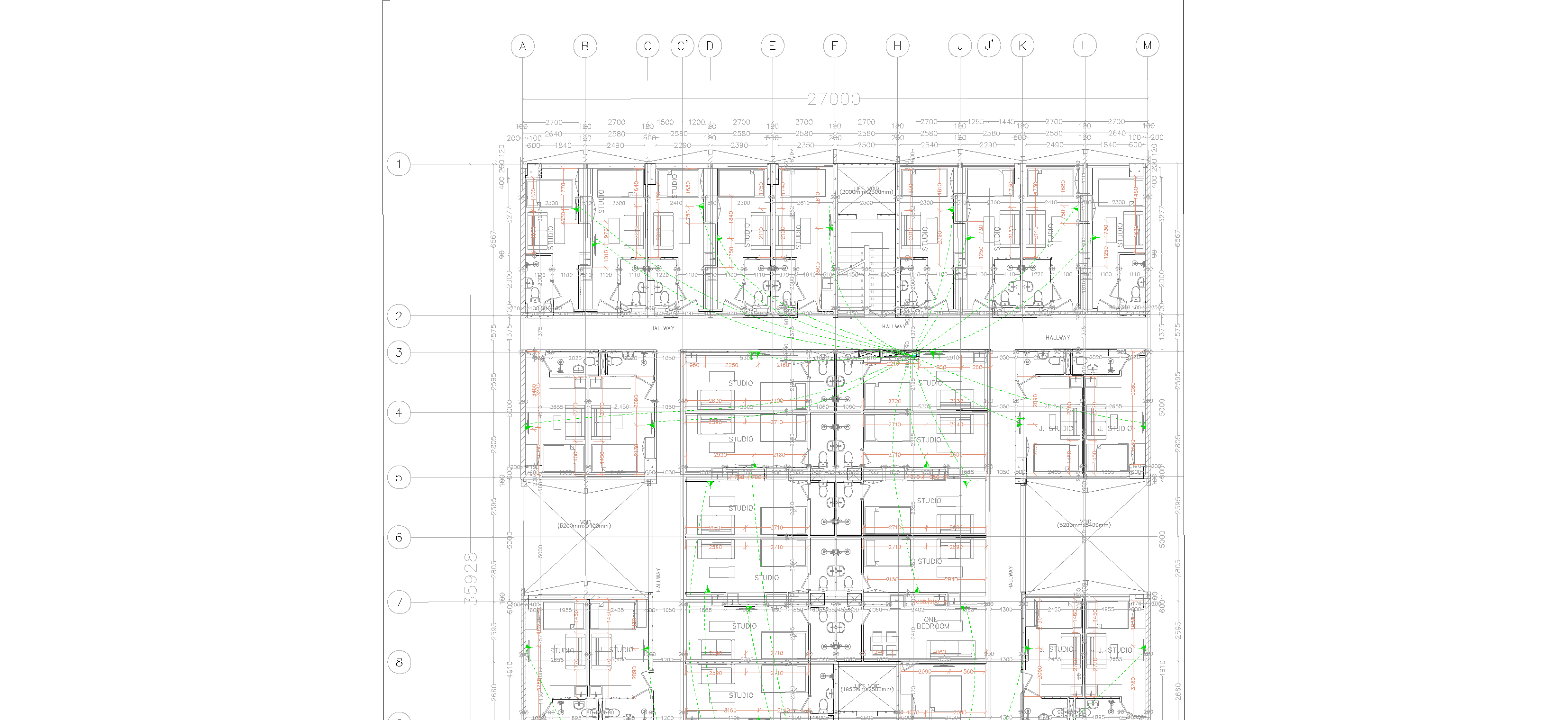
The building's 18 floors split across two riser ducts. Riser A carries 342 units across four 96 core OS2 cables. Riser B carries 324 units across another four. In total, eight 96 core cables bring 768 fiber cores down to the MMR, of which 102 sit spare, a little over 13% headroom for future unit additions or a second fiber run per household.
That spare capacity is not an afterthought. Riser cable is expensive to pull and disruptive to install after a building is occupied. Building in headroom at design stage costs a fraction of retrofitting it later.
Splice closures, not fiber access terminals
On each floor, individual unit fibers branch off the riser backbone through inline splice closures rather than fiber access terminals (FATs). This is a deliberate loss budget decision. A fusion splice loses at most 0.1dB. An LC/UPC connector pair typically loses up to 0.3dB. Multiply that difference across hundreds of connection points on a tall building and it adds up to real optical margin.
The trade off is flexibility. A FAT lets a technician reassign a fiber with a patch cord. A splice closure needs a fusion splicer on site to reconfigure. For a passive network where every unit gets a dedicated home run fiber and reconfiguration is rare, that trade is worth making.
The room itself: two racks, twelve square meters
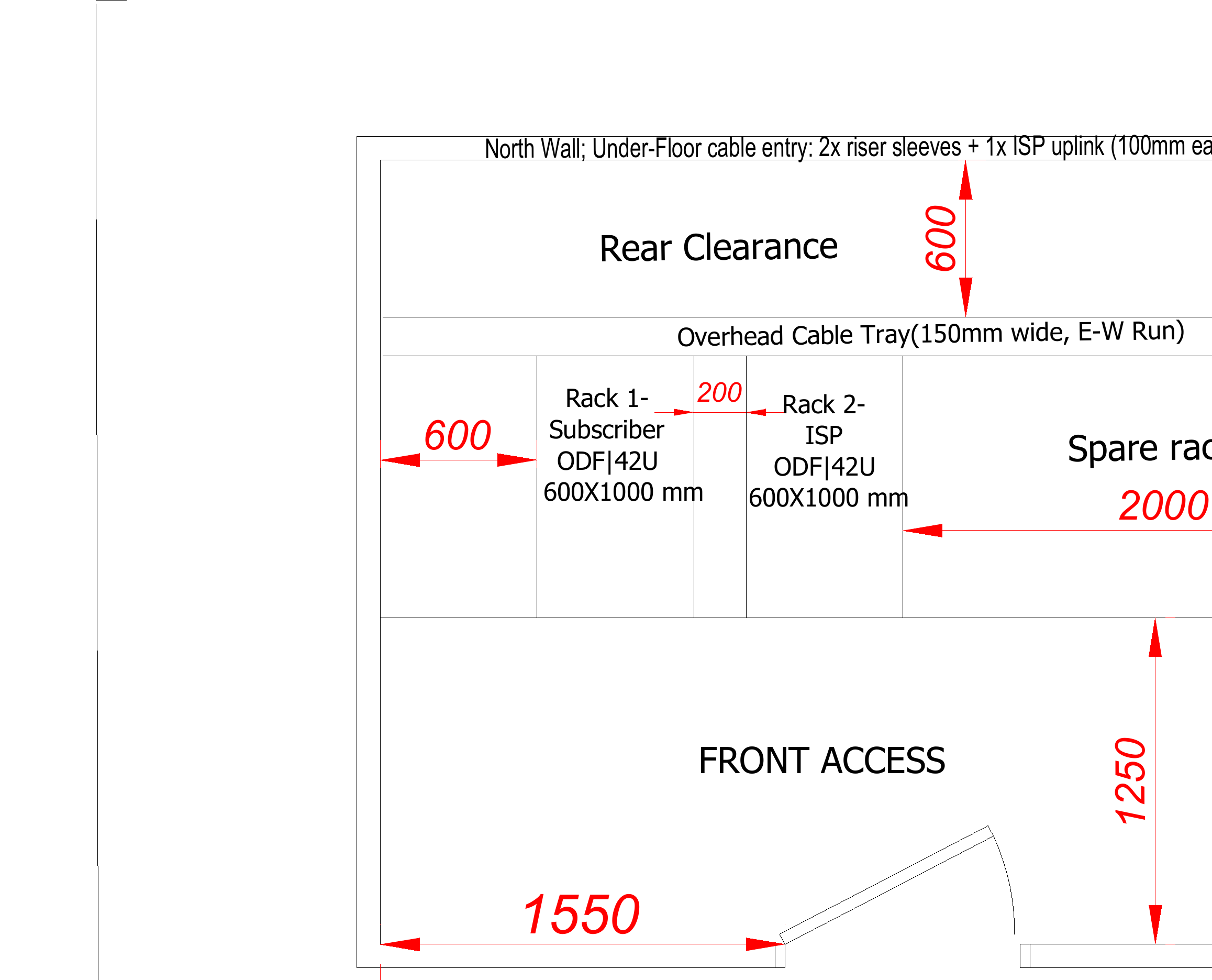
The MMR is a modest 4000mm by 3000mm room housing two 42U racks.
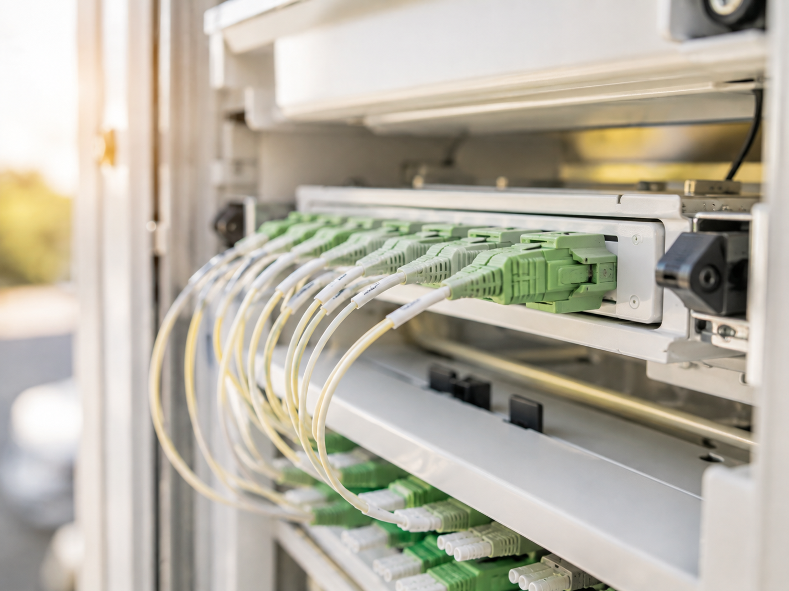
Rack 1 is the subscriber ODF. All 666 building side fibers terminate here on eight 2U, 96 port LC/UPC panels, factory fitted with pigtails. This rack represents the building's fiber plant, organized strictly by riser and by unit range.
Rack 2 is the carrier ODF, the actual handover point to ISPs. It has capacity for three ISPs today with 18U left spare for more. Reassigning a unit from one ISP to another is a single patch cord move between Rack 1 and Rack 2. Nobody needs to touch the riser or open a splice closure to change a resident's provider.
Have a project like this to scope?
A sketch, a photo, or a rough spreadsheet is enough to start.
Start a ProjectLC/UPC was chosen over SC/APC for three practical reasons: it fits 96 ports into 2U where SC/APC would need more rack space, it costs less per port, and it matches the connector type used by the great majority of modern OLT equipment. UPC's return loss, above 50dB, is more than adequate here because splitting and reflection management both happen on the ISP's side of the demarcation, not in the passive MMR.
Why the details matter more than the diagram
A design like this lives or dies on details that never show up in a marketing brochure: 600mm rear clearance for cable dressing, a 150mm galvanised cable tray running east to west above both racks, anti static ESD flooring rated for a room that will see technicians in and out for a decade, three separate under floor conduit sleeves for riser and ISP entry, each fire stopped at the wall.
None of it is glamorous. All of it is the difference between a room that still works cleanly in year ten and one that turns into a tangle nobody wants to open.
What good passive design buys you
By the numbers, this design delivers:
- 768 fiber cores in, 666 units served, 102 spare (13.3% headroom)
- Zero active equipment, zero HVAC load, zero UPS dependency in the MMR
- A one patch cord ISP reassignment process
- Full compliance with ITU-T G.652.D, TIA-568.3-D, TIA-942-B and BICSI TDMM design practices
None of that happens by accident. It happens because someone sat down at the riser schedule stage and decided how many spare cores were worth paying for, and at the rack elevation stage and decided how many spare rack units to leave for a fourth or fifth ISP nobody has signed yet.
That is the part of FTTH design that actually matters once the building is occupied and the marketing brochure is long forgotten.
Related articles
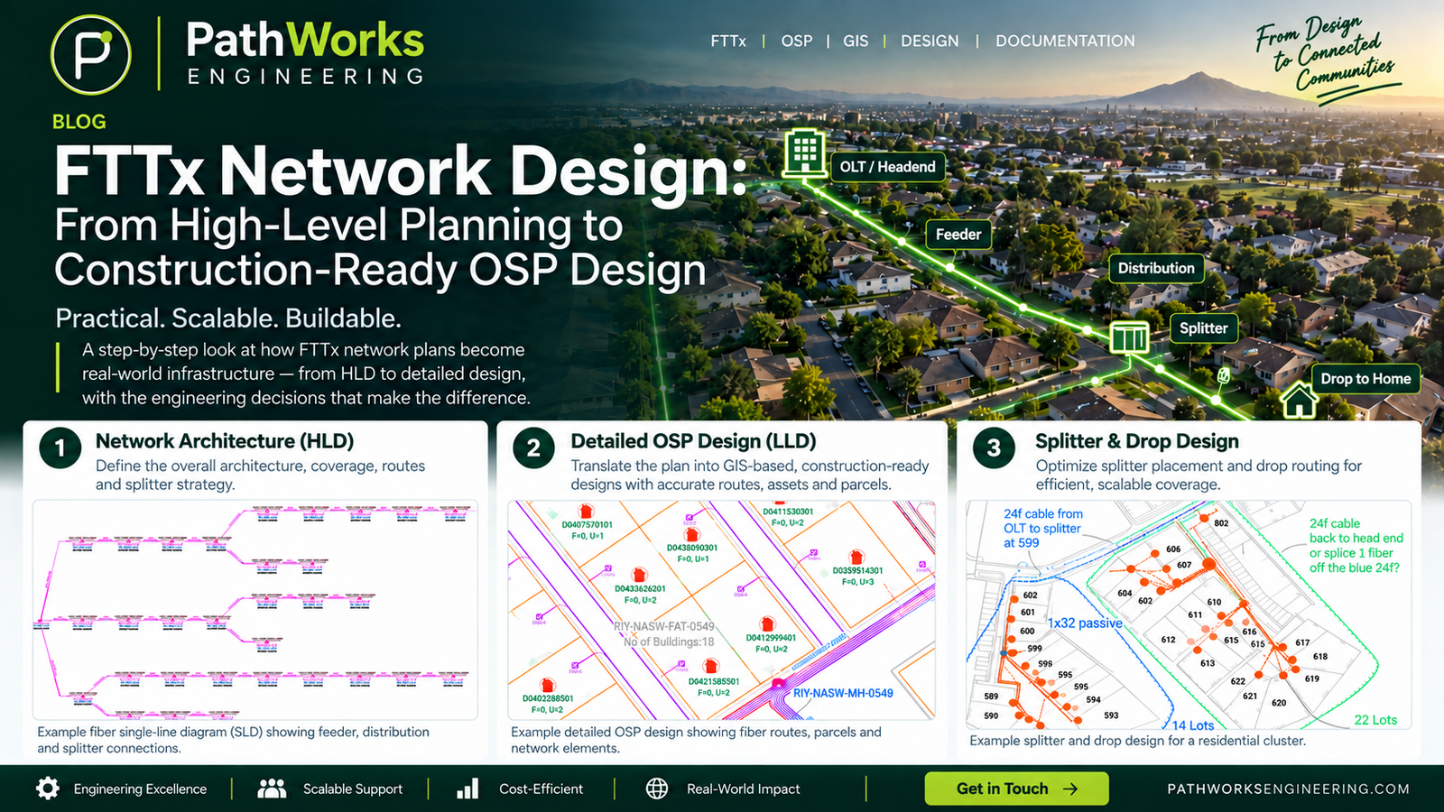

FTTx Network Design: From HLD to Construction-Ready OSP Engineering
A practical guide to FTTx network design, covering HLD, LLD, splitter planning, fiber topology, BOQ development, QA/QC and construction-ready OSP documentation.
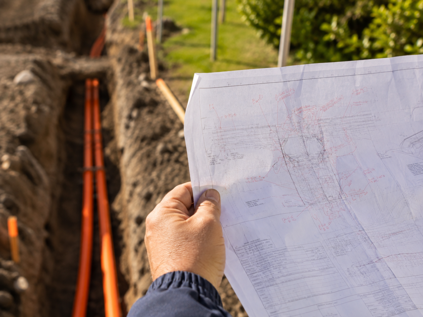
As-Built Redlining: Why the Built Network Stops Matching the Design, and How to Control the Drift
The network in the field and the network on the drawing start drifting apart the moment construction begins. Here's how to control that drift instead of discovering it years later.
GPON Power Budgets: Sizing Split Ratios Against Real Receiver Sensitivity, Not the Datasheet Ceiling
Sizing a split ratio off the datasheet ceiling looks fine on paper and fails in the field. Here's how to budget against real receiver sensitivity instead.